Temperature and Humidity Monitor Using ESP32 and Blynk IOT
DIPLOMA ELECTRONIC ENGINEERING
Prepare by:
- SYAHIDZAL BIN AHMAD SABRI (212011020)
- AINUR ADELIA MAISARAH BINTI AHMAD RIDHAUDIN (212010871)
- NUR AZMINA BINTI FAHURRUZI (212011482)
- WISHAL INSYIRAH BINTI MOHD FAROOK (212011505)
- PANG AII LING (212011488)
INTRODUCTION
Our project uses the IoT Blynk platform and ESP32 microcontroller to create a temperature and humidity monitoring system. The ESP32 is going to be the main device used to gather data from sensors and send it to the Blynk application. Stakeholders will be able to remotely monitor and control environmental conditions thanks to this a connection. The objective of the project is to present a cost-effective and efficient method of temperature and humidity monitoring in a variety of applications including homes, offices, and industrial complexes. The group is excited to share the advancements and learnings made while creating this innovative monitoring system.
OBJECTIVE
- To Provide a convenient and accessible solution for users to check environmental conditions without physically being present at the monitoring location.
- To Minimize the margin of error in data collection to provide reliable and trustworthy information.
- To Utilize IoT protocols and technologies to establish a seamless connection between the monitoring device and a centralized server.
PROBLEM STATEMENT
Current natural observing frameworks confront restrictions in giving opportune and exact information on temperature and stickiness levels, especially within the setting of the Web of Things (IoT). Manual checking strategies are labor-intensive and inclined to human mistake, coming about in deferred reactions to natural varieties. Existing computerized frameworks may need the integration capabilities required for consistent network with IoT systems, constraining their versatility and versatility.
In addition, the nonappearance of a standardized, user-friendly interface postures challenges for end-users endeavoring to decipher and act upon the collected information successfully. In numerous cases, observing arrangements may not offer the essential accuracy, causing inconsistencies in information readings and ruining the unwavering quality of natural evaluations. This need of exactness is particularly basic in businesses, investigate offices, and rural settings where exact natural conditions straightforwardly affect forms and results.
In light of these challenges, the advancement of an IoT-based Temperature and Stickiness Checking venture gets to be basic. The extend points to overcome these confinements by giving a adaptable, precise, and user-friendly arrangement that leverages IoT advances. By tending to these issues, the venture looks for to improve natural observing capabilities, permitting for more educated decision-making, early irregularity discovery, and made strides control over temperature and stickiness conditions in assorted settings.
LITERATURE REVIEW
[1] This paper discusses the design and development of a temperature and humidity monitoring system for agricultural purposes. It explains the components used in the system, such as Arduino Uno, DHT11 sensor, LCD screen, LED bulbs, and a PCB. Field testing results showed that the system had an accuracy of ±2°C for temperature and ±4% for humidity. The total cost of development was ₹1625. The article emphasizes the significance of efficient agricultural practices and the increasing demand for monitoring systems in the agricultural sector.
[2] This paper describes an indoor temperature and humidity monitoring system using IoT technology. The system uses sensors to monitor temperature and humidity levels and transfers data to the cloud for remote access. The data is stored in a database on the cloud, allowing users to track it from anywhere. The system also sends alerts and notifications via the Telegram program for direct control and regulation. When the room temperature or humidity exceeds the set threshold, the system sends a notification to the user, allowing them to send commands to adjust the air conditioner's settings. The system is powered by a Raspberry Pi and an Arduino module. This allows users to have direct control and regulation over the room's temperature and humidity.
[3] The research paper discusses the importance of monitoring humidity and temperature for predicting climate and weather. It proposes a solution using a DHT22 sensor and RF 433 hc12 for precise measurement and data transmission. The DHT22 sensor is reliable and accurate, measuring humidity and temperature in a wide range. Connected to an Arduino Uno microcontroller, it provides digital signals via a 1-wire bus. With high accuracy of +-2%RH for humidity and +-0.5 degrees Celsius for temperature, and a resolution of 0.1%RH for humidity and 0.1 degrees Celsius for temperature, the DHT22 sensor is crucial for accurate data collection and display on an LCD screen.
[4] The paper discusses the use of Internet of Things (IoT) technology to monitor temperature and humidity in a data center. The authors developed a monitoring system using a proposed framework and deployed it in a specific data center. The system recorded and stored readings on an IoT platform. The analysis of the data showed significant differences in temperature and humidity at different locations. The monitoring system was also successful in detecting extreme conditions.
[5] This paper discusses the development of
a prototype device using Arduino Uno to monitor and control temperature and
humidity in a refrigerator, aimed at maintaining food quality in the cold
agri-food chain industry. Current systems for temperature and humidity control
are costly and lack efficient integration. The Arduino Uno device uses a
combination of hardware and software components, including a microcontroller,
DHT11 sensor, ESP8266-01 Wi-Fi module, relay, 12V fan, and 12V battery. The
sensor reads temperature and humidity, and the Arduino Uno processes the data.
The ESP8266-01 Wi-Fi module connects the Arduino Uno to the internet, and the
input data is sent to the 12V fan, which regulates the temperature and
humidity. The Arduino Uno can display the output data through the ThingSpeak
platform, providing a visual representation of temperature and humidity
readings. The prototype offers a cost-effective solution for monitoring and
controlling these parameters in a refrigerator, addressing the challenges in
the cold agri-food chain industry.
METHODOLOGY
1.BLOCK DIAGRAM
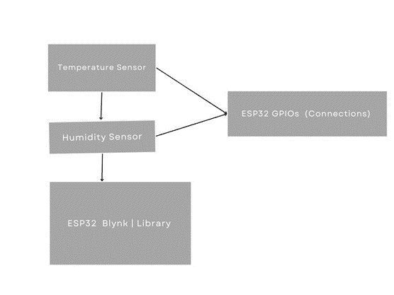
Separate
sensors are employed to detect temperature and humidity, respectively: the
temperature sensor and the humidity sensor. With this connection, they supply
data to the ESP32.The microcontroller known as ESP32 is in charge of gathering
data from the sensors and transmitting it to the Blynk IoT platform. Blynk
Library: This library, which is installed on the ESP32, makes it easier for the
ESP32 and the Blynk app/service to communicate. The physical connections
between the ESP32 and the sensors are represented by the GPIOs (Connections) of
the ESP32. The data pins of the sensors will be linked to the ESP32's GPIO
pins.
2.FLOW CHART


The flowchart for the project begins with the initialization of serial communication, followed by the setup of Wi-Fi and connection to the Blynk server. The DHT sensor is then initialized, and a Blynk timer is set up. In the main loop, the program continuously executes Blynk functions and checks the Blynk timer. If the timer interval has passed, the program enters the sendSensor function. Within this function, it reads temperature and humidity data from the DHT sensor. The flow then diverges: if the data is valid, it updates the Blynk app with the sensor values and prints the temperature and humidity to the serial monitor. Conversely, if the sensor fails to detect valid data, an error message is printed to the serial monitor, stating "Failed to read from DHT sensor." The program then concludes, effectively ending the monitoring process. This flowchart captures the essential steps of initializing, connecting, sensing, and reporting, ensuring robust temperature and humidity monitoring with appropriate error handling.
3.COMPONENT FOR THIS PROJECT(HARDWARE & SOFTWARE)
BREADBOARD
As a flexible platform for electronic circuit testing
and development, a breadboard is a vital instrument in the field of
electronics. A breadboard, which is made out of a plastic foundation with a
grid of linked holes, is a useful tool for quickly and temporarily connecting
different electrical components without the need for soldering. The grid is
made up of rows and columns, each of which has many tie points where integrated
circuits, resistors, and capacitors can be put and linked. An easy way to give
electricity to the components is through power rails that run along the
sidewalls. The breadboard is a great tool for testing out circuit designs
because of its modular and reusable structure, which allows for rapid
iterations and modifications during the development process. This is a very
helpful tool for both novices learning the fundamentals of electronics and
seasoned professionals who are quickly developing new circuits before moving on
to more permanent solutions such as printed circuit boards.

DHT11
A popular and reasonably priced digital temperature
and humidity sensor, the DHT11 is essential to many electronic applications as
well as environmental monitoring. The DHT11 sensor was created with
dependability and simplicity in mind. It can detect relative humidity from 20%
to 90% and ambient temperature from 0 to 50 degrees Celsius (32 to 122 degrees
Fahrenheit). Because it has a calibrated digital signal output, this little
sensor is incredibly simple to interface with digital systems such as
microcontrollers. Weather stations, home automation, and industrial monitoring
are just a few of the applications that have found the DHT11 to be attractive
because to its small size, low power consumption, and simple communication
protocol. The DHT11 sensor is now an accessible option for both hobbyists and
professionals looking for accurate and real-time data on temperature and
humidity conditions because of its user-friendly interface and reasonable price
point.

Jumper
wires
In the realm of electronics and prototyping, jumper
wires are crucial elements that facilitate the smooth exchange of electrical
impulses between different components on a breadboard or other circuit
platforms. These wires, which are usually insulated and include connectors on
both ends, make it easier to create temporary electrical connections without
soldering. An essential tool for assembling circuits, jumper wires enable
engineers, enthusiasts, and amateurs to quickly and easily connect various
components, including microcontrollers, sensors, and other electronic parts.
Jumper wires are essential for rapid circuit design iterations,
experimentation, and prototyping due to their adaptability and simplicity of
usage. Jumper cables are useful when utilised in professional or educational
contexts since they increase efficiency. Jumper wires enhance the flexibility and efficiency of
the electronics design process, facilitating the quick construction and testing
of electronic circuits, whether they are utilised in educational or
professional contexts.

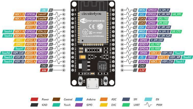
ESP32
In the world of embedded systems and the Internet of
Things, the ESP32 is a well-known and adaptable microcontroller (Internet of
Things). The ESP32, created by Espressif Systems, is well known for its many
GPIO (General Purpose Input/Output) ports, integrated Wi-Fi and Bluetooth
connections, and potent processing capabilities. Based on the Xtensa dual-core
CPU architecture, this microcontroller has become quite popular because to its
ability to handle a broad range of applications, from basic sensor nodes to
intricate Internet of Things projects. Because of its dual-core architecture,
many tasks may be completed at once, improving performance and efficiency. In the quickly
changing world of embedded electronics and Internet of Things applications,
developers, makers, and engineers have come to favour the ESP32 due to its wide
range of features, which include touch sensors, cryptographic acceleration, and
analog-to-digital conversion.
Users with iOS or Android smartphones may control devices like the Arduino, Raspberry Pi, and NodeMCU remotely with the help of the Internet of Things platform Blynk. The application in question is used to create a graphical user interface, or human machine interface (HMI), by compiling and providing the necessary address on the available widgets. Blynk designed with the Internet of Things in mind. It has several incredible ability, including data storage, visualising information, sensor data presentation, and remote hardware control. This technique uses Blynk to send a phone alerts and notify when an email is received.

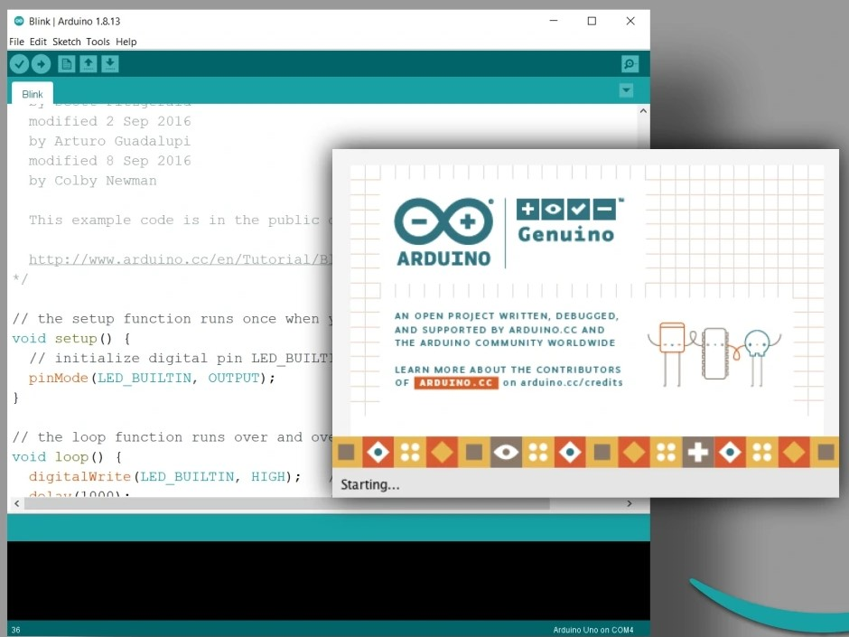
Arduino IDE
Using the Arduino Software (IDE), writing code and uploading it to the device while offline is easy. It is recommended for those with sluggish or nonexistent internet connections. This software functions with any Arduino board. To perform the tasks of the system, a code or programme necessitate to be written and placed inside the ESP32. The Arduino Integrated Development Environment (IDE) software is used to enter the programming code. Readers will be guided through the whole process of writing the computer programmes required to construct this clever temperature and humidity monitor using ESP32 and IOT Blynk in this subtopic. We got the chance to tweak and change the coding we utilised for this project by looking at a few sources.
4.CODING DEVELOPMENT AND EXPLANANTION
The Arduino IDE software was utilised to develop code and simulate the temperature and humidity monitor using ESP32 and IOT Blynk project for this little project. For coding development, using the Arduino IDE to generate the code for our project. Once the code is generated, it is uploaded to the Nodemcu 32s to guarantee correct project functionality. Prior to programming the code, we must declare the libraries that we will be using. The libraries used for this little project are BLYNK_PRINT serial, Wifi.h, and BlynkSimpleEsp32.h.


The
`sendSensor` function reads temperature and humidity values from the DHT
sensor, validates the readings, and transmits the data to the Blynk server for
visualization. The `setup` function initializes serial communication, starts
Blynk, and configures the DHT sensor, while also setting up a timer to
periodically invoke the `sendSensor` function.

sendSensor() every 100 milliseconds.After that,for loop() work as runs the Blynk and timer functions continuously to maintain the connection and trigger the sensor readings.The main loop ensures the continuous operation of
Blynk and the timer, facilitating the real-time monitoring of temperature and
humidity through the Blynk app.
- 5.FULL CODE PROGRAMMING
- #define BLYNK_TEMPLATE_ID "TMPL6Wu4X1ecl" #define BLYNK_TEMPLATE_NAME "Temperature and Humidity Monitor" #define BLYNK_AUTH_TOKEN "2TDswihm4zwYkT6NTmznNwClVzoqxuCt" #define BLYNK_PRINT Serial #include <WiFi.h> //#include <ESP8266WiFi.h> #include <BlynkSimpleEsp32.h> #include <DHT.h> char auth[] = "2TDswihm4zwYkT6NTmznNwClVzoqxuCt"; char ssid[] = "enoq"; // type your wifi name char pass[] = "enoq123456"; // type your wifi password BlynkTimer timer; #define DHTPIN 27 //Connect Out pin to D2 in NODE MCU #define DHTTYPE DHT11 DHT dht(DHTPIN, DHTTYPE); void sendSensor() { float h = dht.readHumidity(); float t = dht.readTemperature(); // or dht.readTemperature(true) for Fahrenheit if (isnan(h) || isnan(t)) { Serial.println("Failed to read from DHT sensor!"); return; } // You can send any value at any time. // Please don't send more that 10 values per second. Blynk.virtualWrite(V0, t); Blynk.virtualWrite(V1, h); Serial.print("Temperature : "); Serial.print(t); Serial.print(" Humidity : "); Serial.println(h); } void setup() { Serial.begin(115200); Blynk.begin(auth, ssid, pass); dht.begin(); timer.setInterval(100L, sendSensor); } void loop() { Blynk.run(); timer.run(); }
RESULT & DISCUSSION
The video focusing on the successful implementation and functionality of the Temperature and Humidity Monitor Using esp8266 and Blynk IOT. When combined with DHT sensors, the ESP32 microcontroller is able to sense changes in humidity and temperature depending on the surrounding conditions. The system analyses the sensor data in response to user interaction with the Blynk app, presenting the current temperature and humidity levels. In addition, the Blynk app design improves accessibility and user experience by giving users a thorough display of temperature and humidity measurements. The device also includes safety measures that inform users in the case that unnecessary environmental conditions are detected, preventing abuse or false data. Ultimately, the system incorporates safety mechanisms to guard prevent data misinterpretation or improper use of the monitoring equipment in an effort to provide a smooth and secure experience. This entails making certain that the
Blynk app displays data accurately and that the sensors perform as anticipated.

CONCLUSION & FUTURE WORK
In summary, it can be concluded that the ESP32 and Blink IoT-based temperature and humidity monitor have accomplished their goals, enabling those working in the agricultural industry to improve productivity. Moreover, the collected data is not only saved but also employed as a resource for forecasting future weather patterns.Despite facing obstacles throughout the development stage, Blink IoT's technical assistance and online materials provided crucial direction that made it feasible to overcome them. After overcoming these obstacles, the project was successfully completed.
It takes an elaborate strategic strategy to meet customer requests. Enabling remote control of humidifiers, heaters, and fans based on the temperature and humidity data collected is a major improvement.The capacity to create extensive automation systems for smart homes is made possible by this feature. Furthermore, users will receive real-time information when temperature or humidity readings exceed predetermined thresholds when threshold-based alerts and notifications are implemented, providing accurate environmental management and monitoring capabilities.
REFERENCES
[1] Sonawane, R. N., Ghule, A. S., Bowlekar, A. P., & Zakane, A. H. (2019). Design and Development of Temperature and Humidity Monitoring System. Agricultural Science Digest, 39(2), 114–118. https://doi.org/10.18805/ag.D-4893
[2] Shamang, K. J., Chukwuma-Uchegbu, M. I., & Sa’id El-nafaty, A. (2020). Indoor Temperature and Humidity Monitoring System. Journal of Science Engineering Technology and Management, 02(05), 50–58. https://doi.org/10.46820/jsetm.2020.2503
[3] Abdulrazzak, I. A., Bierk, H., & Aday, L. A. (2018). Humidity and temperature monitoring. International Journal of Engineering & Technology, 7(4), 5174–5177. https://doi.org/10.14419/ijet.v7i4.23225
[4] Rahman, R. A., Hashim, U. R., & Ahmad, S. (2020). IoT based temperature and humidity monitoring framework. Bulletin of Electrical Engineering and Informatics, 9(1), 229–237. https://doi.org/10.11591/eei.v9i1.1557
[5] Noraziz, M. K. I., Yusof, E. M. M., &
Yahya, N. (2021). Iot-Based Temperature and Humidity Control in a Refrigerator
Using Arduino Uno. Malaysian Journal of Industrial Technology, 5(2),
31–35.
Comments
Post a Comment